Indicators on Wedge Barriers You Should Know

18 might be done a lot more rapidly, quickly, and price properly. FIG. In specific personifications, the support 30 may be a steel frame consisting of plates, beam of lights(e. g., I-beams ), and/or various other structures that are protected within the foundation 14, which may be concrete. At the surface 12, an upper side 28 of the anchor 30 might go to least partly revealed
, thus making it possible for the add-on of the obstacle 10 to the support 30. g., threaded openings)in several beams or plates of the support 30 may be exposed to the surface 12. In this way, screws 32 or other mechanical fasteners may be used to secure the barrier 10 to the anchor 30. As the obstacle 10 is installed to the surface 12 of the structure 14, collection of debris and other material below the barrier might be minimized, and parts of the bather 10 may not be subjected to below grade environments. As shown by reference character 52, the training device 50 consists of elements got rid of under the wedge plate 16. For instance, the parts 52 under the wedge plate 16 may consist of an electromechanical actuator, a webcam, several web cam surface areas, etc. Additionally, the lifting mechanism 50 includes a springtime assembly 54
The springtime pole 58 is paired to a web cam(e. g., webcam 80 revealed in FIG. 4) of the training mechanism 50. The springtimes 60 disposed concerning the spring rod 58 are kept in compression by springtime supports 62, consisting of a dealt with springtime support 64. That is, the fixed springtime support 64 is dealt with relative to the structure 14 and the remainder of the bather 10.
Little Known Facts About Wedge Barriers.
The continuing to be force applied to
the cam camera deploy the wedge plate 16 may be provided offered an electromechanical actuator 84 or other various other. The springtime assembly 54 and the actuator 84(e. Wedge Barriers. g., electromechanical actuator)might run together to convert the webcam and lift the wedge plate 16.
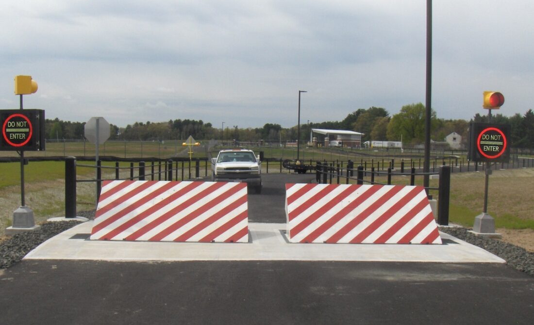
As discussed over, the spring assembly 54 applies a constant force on the cam, while the electromechanical actuator might be managed to exert a variable force on the webcam, consequently enabling the training and decreasing( i. e., releasing and withdrawing )of the wedge plate 16. In specific personifications, the continuous force used by the spring assembly 54 may be flexible. g., electromechanical actuator) is handicapped. As will certainly be valued, the springtime setting up 54 might be covered and safeguarded from debris or other elements by a cover plate(e. g., cover plate 68 displayed in FIG. 4) that might be considerably flush with the raised surface area 38 of the structure 14. As discussed over, in the released setting, the wedge plate 16 serves to obstruct access or traveling beyond the obstacle 10. For example, the obstacle 10(e. g., the wedge plate 16 )might obstruct pedestrians or lorries from accessing a property or pathway. As site web reviewed over, the barrier 10 is affixed to the support 30 safeguarded within the structure 14,

front brackets 71. Consequently, the affiliation settings up 72 might pivot and turn to make it possible for the collapse and expansion of the affiliation settings up 72 during retraction and release of the bather 10. The link settings up 72 reason movement of the wedge plate 16 to be restricted. If a lorry is traveling in the direction of the released wedge plate 16(e. For example, in one circumstance, the security legs 86 may be prolonged throughoutmaintenance of the barrier 10. When the security legs 86 are released, the safety legs 86 support the weight of the wedge plate 16 against the surface area 12. Therefore, the training system 50 might be shut off, serviced, removed, replaced, and so forth. FIG. 5 is partial viewpoint sight of a personification of the surface-mounted wedge-style barrier 10, illustrating the webcam 80 and the web cam surface areas 82 of the training device 50. Specifically, 2 cam surface areas 82, which are referred to as reduced cam surfaces 83, are placed listed below the web cam 80. The lower cam surfaces 83 might be repaired to the surface area 12 (e. For example, the lower camera surface areas 83 and the installing plate 85 might form a solitary piece Check This Out that is safeguarded to the anchor 30 by screws or other mechanical fasteners. Additionally, two cam surface areas 82, which are described as upper web cam surface Bonuses areas 87, are positioned over the web cam 80 and coupled to (e. In other personifications, stepping in layers or plates may be placed between the surface area 12 and the reduced webcam surface areas 83 and/or the wedge plate 16 and the top webcam surfaces 87 As discussed over, the cam
80 translates along the cam surfaces 82 when the wedge plate 16 is raised from the pulled back position to the released setting. Additionally, as mentioned over, the spring setting up 54 (see FIG. 3 )may provide a pressure acting upon the webcam 80 in the instructions 102 using springtime pole 58, which may decrease the pressure the electromechanical actuator 84 is required to use to the cam 80 in order to actuate and lift the wedge plate 16. 1 )to the released placement(see FIG. 4). As revealed, the cam 80 consists of track wheels 104(e. g., rollers), which contact and translate along the cam surface areas 82 during procedure.